User Tools
Sidebar
electronics:multiplexing_leds
Table of Contents
Controlling LED's by multiplexing
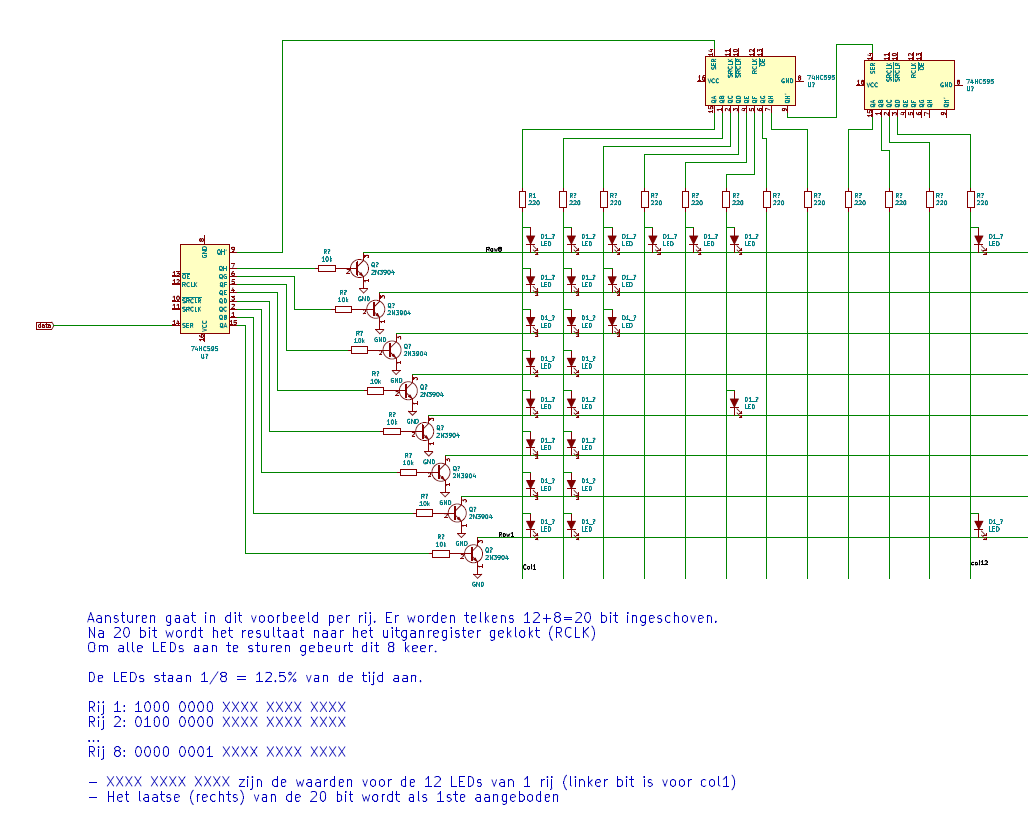
Lighting a grid of LEDs by using multiplexing consists of providing current to them row by row (or columns by column). In this way the LEDs are not lit 100 % of the time. For 8 rows the current to a 'ON' LED is flowing only 1/8 = 12.5 % of the time.
- the advantage of multiplexing is having less wires and components.
- if alternating the rows is fast enough, no flicker is visible. In practice 100 Hz is enough.
- the LEDs are less bright than a LED that is on 100 % of the time. This can be compensated by choosing a higher current.
Below is an example schema. The rows and columns are controlled by shift registers to reduce the number of needed GPIO pins.

Experiment
A simplified version of this circuit (no transistors but higher valued resistors) was implemented on a breadboard to control a 8×8 LED matrix.
Code
The shift registers were fed by an Arduino Nano. The code is shown below.
int latchPin = 8;
int clockPin = 12;
int dataPin = 11;

void setup() {
  // put your setup code here, to run once:
  pinMode(latchPin, OUTPUT);
  pinMode(clockPin, OUTPUT);
  pinMode(dataPin, OUTPUT);

  digitalWrite(latchPin, LOW);
  digitalWrite(clockPin, LOW);
  digitalWrite(dataPin, LOW);

  Serial.begin(9600);
  Serial.println("reset");
}

unsigned char col[] = {  // 8x8 smiley
  0b01111110,
  0b10000001,
  0b10100101,
  0b10000001,
  0b10100101,
  0b10011001,
  0b10000001,
  0b01111110,
};

int row = 0;
void loop() {
  digitalWrite(latchPin, LOW);
  digitalWrite(clockPin, LOW);
  // Switching between MSBFIRST and LSBFIRST mirrors or flips the pattern
  shiftOut(dataPin, clockPin, MSBFIRST, 1<<row);
  // invert data: no transitor, writing lights led
  shiftOut(dataPin, clockPin, MSBFIRST, ~col[row]);
  digitalWrite(latchPin, HIGH);

  row++;
  if (row>7) row=0;
  delay(1);
}
Notes
- the transistors are needed because the shift register outputs ar not able to sink enough current for a whole row. An economic alternative would be to replace the 74HC595 that controls the rows by a tpic6b595 ('power' shift register with builtin transistors)
- Technically the column sift registers also need external transistors: the outputs can handle a LED, but the chip cannot officially handle the total current for 8 LEDs (according to the data sheets max total current is 70 mA). A safe solution would be to limit the current per LED to 8 mA, probably bright enough indoor.
- resistors and transistors are available grouped in small packages. This reduces costs an space when not using SMD components.
- when building a prototype, do not forget to add capacitors to stabilize the 5V power (100 uF + 100 nF close to each integrated circuit)
electronics/multiplexing_leds.txt · Last modified: by 127.0.0.1


